Membrane sculpting by curved DNA origami scaffolds

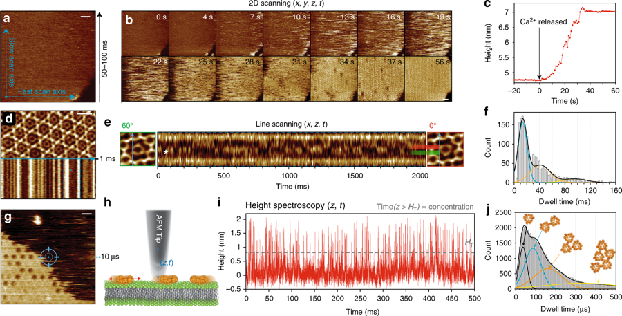
In the article “Membrane sculpting by curved DNA origami scaffolds” the authors show that “dependent on curvature, membrane affinity and surface density, DNA origami coats can indeed reproduce the activity of membrane-sculpting proteins such as BAR, suggesting exciting perspectives for using them in bottom-up approaches towards minimal biomimetic cellular machineries.”*

The AFM images for this article were taken in high-speed AC mode using NanoWorld Ultra-Short Cantilevers of the USC-F0.3-k0.3 type.

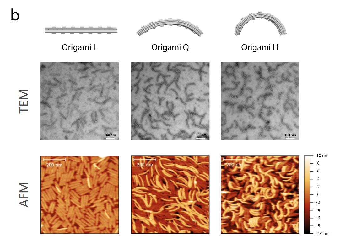
Supplementary Figure 5 b from Membrane sculpting by curved DNA origami scaffolds: Characterization of folded DNA origami nanoscaffolds. ( a ) Assembly of the folded bare origami structures L, Q, H was initially assessed via agarose gel (2%) electrophoresis analysis. Lanes containing marker DNA ladder (1kb) and M13 single - stranded p7249 sc affold (Sc) were also included. ( b ) Structure of folded bare origami L, Q and H was further validated using negative - stain transmission electron microscopy (TEM ; scale bar s : 100 nm ) and atomic force microscopy (AFM ; scale bar s : 200nm ).
Supplementary Figure 5 b from “Membrane sculpting by curved DNA origami scaffolds”:
Characterization of folded DNA origami nanoscaffolds.
b) Structure of folded bare origami L, Q and H was further validated using negative-stain transmission electron microscopy (TEM; scale bars: 100 nm) and atomic force microscopy (AFM; scale bars: 200nm).

*Henri G. Franquelim, Alena Khmelinskaia, Jean-Philippe Sobczak, Hendrik Dietz, Petra Schwille
Membrane sculpting by curved DNA origami scaffolds
Nature Communicationsvolume 9, Article number: 811 (2018)
DOI: https://doi.org/10.1038/s41467-018-03198-9

Please follow this link to the full article: https://rdcu.be/8zZi

Open Access: The article “Membrane sculpting by curved DNA origami scaffolds” by Franquelim et. al is licensed under a Creative Commons Attribution 4.0 International License, which permits use, sharing, adaptation, distribution and reproduction in any medium or format, as long as you give appropriate credit to the original author(s) and the source, provide a link to the Creative Commons license, and indicate if changes were made. The images or other third party material in this article are included in the article’s Creative Commons license, unless indicated otherwise in a credit line to the material. If material is not included in the article’s Creative Commons license and your intended use is not permitted by statutory regulation or exceeds the permitted use, you will need to obtain permission directly from the copyright holder. To view a copy of this license, visit http://creativecommons.org/licenses/by/4.0/.

Vertical Light Sheet Enhanced Side-View Imaging for AFM Cell Mechanics Studies

Atomic Force Microscopy is a powerful tool for evaluating cell mechanics.
In the recent article “Vertical Light Sheet Enhanced Side-View Imaging for AFM Cell Mechanics Studies” by Kellie Beicker, E. Timothy O’Brien III, Michael R. Falvo, Richard Superfine published in Nature Scientific Reports, the authors combine sideways imaging and a vertical light sheet illumination system integrated with AFM to achieve their results.

5 µm polystyrene beads attached to NanoWorld Arrow-TL1 tipless AFM probes were used.

igure 5 from Vertical Light Sheet Enhanced Side-View Imaging for AFM Cell Mechanics Studies: Membrane and nuclear displacements observed in response to force-rupture events between the AFM-tip and cell membrane. (a) Retraction portion of force-indentation curve with important points (A-G) identified. A, the point of zero force application to the cell, B-F, force-rupture peaks, and G, after bead releases from cell. (b) A closer examination of peaks E and F with sub-peaks of the E rupture event identified. No point is shown for E1 because this is the frame immediately following Peak E0. Inset indicates regions where displacement is measured between points E and F highlighted in green. These regions were determined through difference imaging using frames taken at E and F. (c) Regions of cell displacements determined through difference imaging highlighted in green for the sub-peaks indicated in (b). Yellow dashed lines indicate outline of AFM mounted bead. Scale bars = 5 um. NanoWorld Arrow-TL1 tipless AFM cantilevers were used.
Figure 5 from Beicker et. al Vertical Light Sheet Enhanced Side-View Imaging for AFM Cell Mechanics Studies: Membrane and nuclear displacements observed in response to force-rupture events between the AFM-tip and cell membrane. (a) Retraction portion of force-indentation curve with important points (A-G) identified. A, the point of zero force application to the cell, B-F, force-rupture peaks, and G, after bead releases from cell. (b) A closer examination of peaks E and F with sub-peaks of the E rupture event identified. No point is shown for E1 because this is the frame immediately following Peak E0. Inset indicates regions where displacement is measured between points E and F highlighted in green. These regions were determined through difference imaging using frames taken at E and F. (c) Regions of cell displacements determined through difference imaging highlighted in green for the sub-peaks indicated in (b). Yellow dashed lines indicate outline of AFM mounted bead. Scale bars = 5 um.

Kellie Beicker, E. Timothy O’Brien III, Michael R. Falvo, Richard Superfine
Vertical Light Sheet Enhanced Side-View Imaging for AFM Cell Mechanics
Studies
Nature Scientific Reports, volume 8, Article number: 1504 (2018)
DOI: https://doi.org/10.1038/s41598-018-19791-3

For the full article please follow this external link: https://rdcu.be/59FM

The article Beicker et. al, Vertical Light Sheet Enhanced Side-View Imaging for AFM Cell Mechanics Studies is licensed under a Creative Commons Attribution 4.0 International License, which permits use, sharing, adaptation, distribution and reproduction in any medium or format, as long as you give appropriate credit to the original author(s) and the source, provide a link to the Creative Commons license, and indicate if changes were made. The images or other third party material in this article are included in the article’s Creative Commons license, unless indicated otherwise in a credit line to the material. If material is not included in the article’s Creative Commons license and your intended use is not permitted by statutory regulation or exceeds the permitted use, you will need to obtain permission directly from the copyright holder. To view a copy of this license, visit http://creativecommons.org/licenses/by/4.0/.


Mussel adhesion is dictated by time-regulated secretion and molecular conformation of mussel adhesive proteins

We have a month with “R” again and the shellfish season has started in the Northern Hemisphere. So we’d like to share the Nature Communications article by Petrone et. al “Mussel adhesion is dictated by time-regulated secretion and molecular conformation of mussel adhesive proteins” with you.
A NanoWorld Pointprobe® NCSTR AFM probe was used for the AFM images in this paper. This AFM probe is designed to give extra stability and accuracy during soft tapping mode imaging in order to produce higher quality AFM images while minimizing sample damage.

Supplementary Figure 16 from Petrone et. al "Mussel adhesion is dictated by time-regulated secretion and molecular conformation of mussel adhesive proteins": Atomic Force Microscopy (AFM) of mussel adhesive proteins on mica. AFM images of dry Pvfp-3α and Pvfp-5β adsorbed from 0.02 mg ml-1 solution in 5% acetic acid and 0.25 MO3 on mica. After 20 min adsorption, the mica surfaces were washed with protein -free buffer, and the AFM images show the homogenous distribution of the resulting adsorbed proteins. The height profiles for both proteins are shown in the graphs below, corresponding to the dotted red and blue lines in the respective AFM images (see black arrows).
Supplementary Figure 16 from Petrone et. al “Mussel adhesion is dictated by time-regulated
secretion and molecular conformation of mussel adhesive proteins”:
Atomic Force Microscopy (AFM) of mussel adhesive proteins on mica. AFM images of dry Pvfp-3α and Pvfp-5β adsorbed from 0.02 mg ml-1 solution in 5% acetic acid and 0.25 MO3 on mica. After 20 min adsorption, the mica surfaces were washed with protein -free buffer, and the AFM images show the homogenous distribution of the resulting adsorbed proteins. The height profiles for both proteins are shown in the graphs below, corresponding to the dotted red and blue lines in the respective AFM images (see black arrows).

Luigi Petrone, Akshita Kumar, Clarinda N. Sutanto, Navinkumar J. Patil, Srinivasaraghavan Kannan, Alagappan Palaniappan, Shahrouz Amini, Bruno Zappone, Chandra Verma, Ali Miserez
Mussel adhesion is dictated by time-regulated secretion and molecular conformation of mussel adhesive proteins
Nature Communications volume 6, Article number: 8737 (2015)
DOI https://doi.org/10.1038/ncomms9737

Please follow this external link for the full article: https://rdcu.be/5vcI

The article by Petrone, L.et al. “Mussel adhesion is dictated by time-regulated secretion and molecular conformation of mussel adhesive proteins” is licensed under a Creative Commons Attribution 4.0 International License. The images or other third party material in this article are included in the article’s Creative Commons license, unless indicated otherwise in the credit line; if the material is not included under the Creative Commons license, users will need to obtain permission from the license holder to reproduce the material. To view a copy of this license, visit http://creativecommons.org/licenses/by/4.0/