Chemical switching of low-loss phonon polaritons in α-MoO3 by hydrogen intercalation

Phonon polaritons (PhPs) have attracted significant interest in the nano-optics communities because of their nanoscale confinement and long lifetimes. Although PhP modification by changing the local dielectric environment has been reported, controlled manipulation of PhPs by direct modification of the polaritonic material itself has remained elusive.*

In the article “Chemical switching of low-loss phonon polaritons in α-MoO3 by hydrogen intercalation” Yingjie Wu, Qingdong Ou, Yuefeng Yin, Yun Li, Weiliang Ma, Wenzhi Yu, Guanyu Liu, Xiaoqiang Cui, Xiaozhi Bao, Jiahua Duan, Gonzalo Álvarez-Pérez, Zhigao Dai, Babar Shabbir, Nikhil Medhekar, Xiangping Li, Chang-Ming Li, Pablo Alonso-González and Qiaoliang Bao demonstrate an effective chemical approach to manipulate PhPs in α-MoO3 by the hydrogen intercalation-induced perturbation of lattice vibrations.*

Their methodology establishes a proof of concept for chemically manipulating polaritons, offering opportunities for the growing nanophotonics community.*

The surface topography and near-field images presented in this article were captured using a commercial s-SNOM setup with a platinum iridium coated NanoWorld Arrow-NCPt AFM probe in tapping mode.*

Fig. 2 a) from “Chemical switching of low-loss phonon polaritons in α-MoO3 by hydrogen intercalation” by Yingjie Wu et al. :
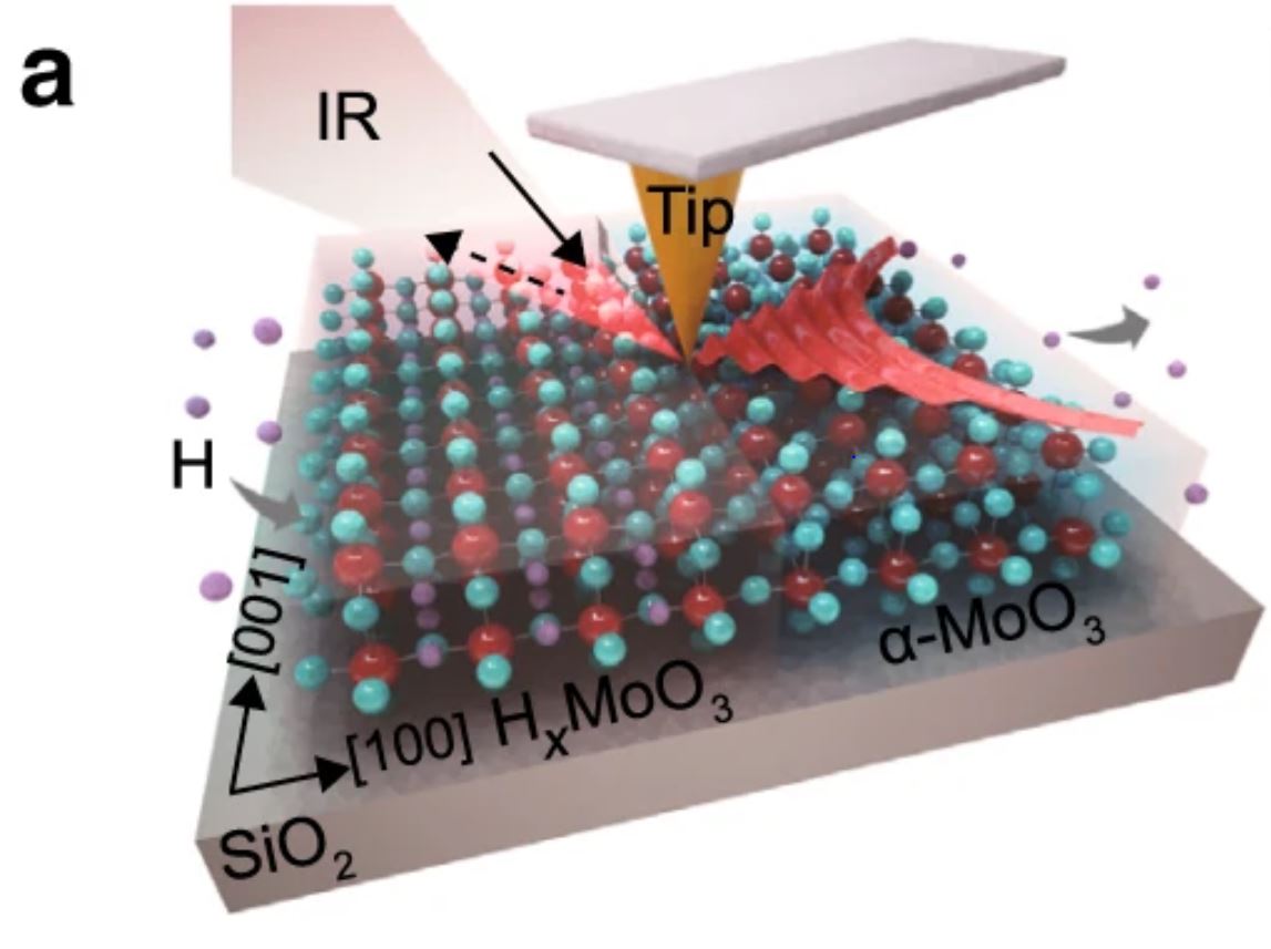
Reversible switching of PhPs in the L-RB of α-MoO3 a Schematic of the s-SNOM measurement and PhP propagation in a typical H-MoO3/α-MoO3 in-plane heterostructure.
2 a Schematic of the s-SNOM measurement and PhP propagation in a typical H-MoO3/α-MoO3 in-plane heterostructure. P
Fig. 2 a) from “Chemical switching of low-loss phonon polaritons in α-MoO3 by hydrogen intercalation” by Yingjie Wu et al. :
Reversible switching of PhPs in the L-RB of α-MoO3 a Schematic of the s-SNOM measurement and PhP propagation in a typical H-MoO3/α-MoO3 in-plane heterostructure.
2 a Schematic of the s-SNOM measurement and PhP propagation in a typical H-MoO3/α-MoO3 in-plane heterostructure. Please follow this external link for the full figure: https://www.nature.com/articles/s41467-020-16459-3/figures/2

*Yingjie Wu, Qingdong Ou, Yuefeng Yin, Yun Li, Weiliang Ma, Wenzhi Yu, Guanyu Liu, Xiaoqiang Cui, Xiaozhi Bao, Jiahua Duan, Gonzalo Álvarez-Pérez, Zhigao Dai, Babar Shabbir, Nikhil Medhekar, Xiangping Li, Chang-Ming Li, Pablo Alonso-González & Qiaoliang Bao
Chemical switching of low-loss phonon polaritons in α-MoO3 by hydrogen intercalation
Nature Communications volume 11, Article number: 2646 (2020)
DOI: https://doi.org/10.1038/s41467-020-16459-3

Please follow this external link to read the full article https://rdcu.be/b46eT

Open Access The article “ Chemical switching of low-loss phonon polaritons in α-MoO3 by hydrogen intercalation “ by Yingjie Wu, Qingdong Ou, Yuefeng Yin, Yun Li, Weiliang Ma, Wenzhi Yu, Guanyu Liu, Xiaoqiang Cui, Xiaozhi Bao, Jiahua Duan, Gonzalo Álvarez-Pérez, Zhigao Dai, Babar Shabbir, Nikhil Medhekar, Xiangping Li, Chang-Ming Li, Pablo Alonso-González and Qiaoliang Bao is licensed under a Creative Commons Attribution 4.0 International License, which permits use, sharing, adaptation, distribution and reproduction in any medium or format, as long as you give appropriate credit to the original author(s) and the source, provide a link to the Creative Commons license, and indicate if changes were made. The images or other third party material in this article are included in the article’s Creative Commons license, unless indicated otherwise in a credit line to the material. If material is not included in the article’s Creative Commons license and your intended use is not permitted by statutory regulation or exceeds the permitted use, you will need to obtain permission directly from the copyright holder. To view a copy of this license, visit http://creativecommons.org/licenses/by/4.0/.

Launching of hyperbolic phonon-polaritons in h-BN slabs by resonant metal plasmonic antennas

Launching and manipulation of polaritons in van der Waals materials offers novel opportunities for applications such as field-enhanced molecular spectroscopy and photodetection.*

Particularly, the highly confined hyperbolic phonon polaritons (HPhPs) in h-BN slabs attract growing interest for their capability of guiding light at the nanoscale. An efficient coupling between free space photons and HPhPs is, however, hampered by their large momentum mismatch.*

In the article “Launching of hyperbolic phonon-polaritons in h-BN slabs by resonant metal plasmonic antennas” P. Pons-Valencia, F. J. Alfaro-Mozaz, M. M. Wiecha, V. Biolek, I. Dolado, S. Vélez,P. Li, P. Alonso-González, F. Casanova, L. E. Hueso, L. Martín-Moreno, R. Hillenbrand and A. Y. Nikitin show that resonant metallic antennas can efficiently launch HPhPs in thin h-BN slabs. Despite the strong hybridization of HPhPs in the h-BN slab and Fabry-Pérot plasmonic resonances in the metal antenna, the efficiency of launching propagating HPhPs in h-BN by resonant antennas exceeds significantly that of the non-resonant ones.

Their results provide fundamental insights into the launching of HPhPs in thin polar slabs by resonant plasmonic antennas, which will be crucial for phonon-polariton based nanophotonic devices.*

A commercial s-SNOM setup in which the oscillating (at a frequency Ω≅270kHz) metal-coated (Pt/Ir) AFM tip (NanoWorld ARROW-NCPt) was illuminated by p-polarized mid-IR radiation, was used.*

 Figure 4 from “Launching of hyperbolic phonon-polaritons in h-BN slabs by resonant metal plasmonic antennas” by P. Pns-Valencia et al. : 
 Near-field imaging of the HPhPs launched by the gold antenna. a Schematics of the s-SNOM setup. b Illustration of antenna launching of HPhPs. The spatial distribution of the near-field (shown by the red and blue colors) is adapted from the simulation of Re(Ez). c Topography of the antenna. d Simulated near-field distribution, |E(x, y)|, created by the rod antenna on CaF2 (the field is taken at the top surface of the antenna). Scale bars in c, d are 0.5 μm. e, h Experimental near-field images. f, i Simulated near-field distribution |Ez(x, y)| (taken 150 nm away from the h-BN slab). g, j Simulated near-field distribution |Ez(z, y)| taken in the cross-section plane along the center of the rod antenna. In e–g ω = 1430 cm−1, while in h–j ω = 1515 cm−1. The scale bars in e–i are 2 μm and in g, j are 0.1 μm (vertical) and 0.5 μm (horizontal). The length of the antenna in all panels is L = 2.29 μm

Figure 4 from “Launching of hyperbolic phonon-polaritons in h-BN slabs by resonant metal plasmonic antennas” by P. Pons-Valencia et al. :
Near-field imaging of the HPhPs launched by the gold antenna. a Schematics of the s-SNOM setup. b Illustration of antenna launching of HPhPs. The spatial distribution of the near-field (shown by the red and blue colors) is adapted from the simulation of Re(Ez). c Topography of the antenna. d Simulated near-field distribution, |E(x, y)|, created by the rod antenna on CaF2 (the field is taken at the top surface of the antenna). Scale bars in c, d are 0.5 μm. e, h Experimental near-field images. f, i Simulated near-field distribution |Ez(x, y)| (taken 150 nm away from the h-BN slab). g, j Simulated near-field distribution |Ez(z, y)| taken in the cross-section plane along the center of the rod antenna. In e–g ω = 1430 cm−1, while in h–j ω = 1515 cm−1. The scale bars in e–i are 2 μm and in g, j are 0.1 μm (vertical) and 0.5 μm (horizontal). The length of the antenna in all panels is L = 2.29 μm

*P. Pons-Valencia, F. J. Alfaro-Mozaz, M. M. Wiecha, V. Biolek, I. Dolado, S. Vélez,P. Li, P. Alonso-González, F. Casanova, L. E. Hueso, L. Martín-Moreno, R. Hillenbrand, A. Y. Nikitin
Launching of hyperbolic phonon-polaritons in h-BN slabs by resonant metal plasmonic antennas
Nature Communications 2019; 10: 3242
doi: 10.1038/s41467-019-11143-7

Please follow this external link to read the full article: https://www.ncbi.nlm.nih.gov/pmc/articles/PMC6642108/

Open Access: The paper « Launching of hyperbolic phonon-polaritons in h-BN slabs by resonant metal plasmonic antennas » by P. Pons-Valencia, F. J. Alfaro-Mozaz, M. M. Wiecha, V. Biolek, I. Dolado, S. Vélez,P. Li, P. Alonso-González, F. Casanova, L. E. Hueso, L. Martín-Moreno, R. Hillenbrand and A. Y. Nikitin is licensed under a Creative Commons Attribution 4.0 International License, which permits use, sharing, adaptation, distribution and reproduction in any medium or format, as long as you give appropriate credit to the original author(s) and the source, provide a link to the Creative Commons license, and indicate if changes were made. The images or other third party material in this article are included in the article’s Creative Commons license, unless indicated otherwise in a credit line to the material. If material is not included in the article’s Creative Commons license and your intended use is not permitted by statutory regulation or exceeds the permitted use, you will need to obtain permission directly from the copyright holder. To view a copy of this license, visit http://creativecommons.org/licenses/by/4.0/.
Boron nitride nanoresonators for phonon-enhanced molecular vibrational spectroscopy at the strong coupling limit

In the article “Boron nitride nanoresonators for phonon-enhanced molecular vibrational spectroscopy at the strong coupling limit” the authors use, for the first time, phonon-polariton-resonant h-BN ribbons for SEIRA spectroscopy of small amounts of organic molecules in Fourier transform infrared spectroscopy. They demonstrate a new way to strongly couple infrared light and molecular vibrations, by utilizing phonon polariton nanoresonators made of hexagonal boron nitride, a Van der Waals material.

For the nanoscale Fourier transform infrared (nano-FTIR) spectroscopy mentioned in this article an oscillating Pt/Ir coated NanoWorld Arrow-NCPt AFM probe was illuminated by p-polarized mid-IR broadband radiation.

Figure 2 from "Boron nitride nanoresonators for phonon-enhanced molecular vibrational spectroscopy at the strong coupling limit": Far- and near-field spectroscopic characterization of h-BN ribbon arrays. (a) Sketch of the transmission spectroscopy experiment. Incoming light at normal incidence is polarized perpendicular to the ribbons to excite the HPhP resonance. (b) Transmission spectrum normalized to the bare substrate spectrum, T/T0, for a 20 × 20 μm2 h-BN ribbon array. Ribbon width w=158 nm, ribbon period D=400 nm and ribbon height h=40 nm. (c) Sketch of the nano-FTIR spectroscopy experiment. The near-field probing tip is scanned across (y-direction) the h-BN ribbon in 20-nm steps, as indicated by the dashed blue line. Near-field spectra are recorded as a function of the tip position (the detector signal is demodulated at the third harmonic of the tip tapping frequency, yielding s3(y, ω), as explained in the Materials and methods section). (d) Lower panel: Spectral line scan s3(y, ω), where each horizontal line corresponds to a spectrum recorded at a fixed y-position (vertical axis). Upper panel: Illustration of the real part of the z-component of the electric field (Re[Ez]) profile across the ribbon at the resonance frequency observed in the nano-FTIR spectra (lower panel). The AFM tip used was a NanoWorld Arrow-NCPT
Figure 2 from “Boron nitride nanoresonators for phonon-enhanced molecular vibrational spectroscopy at the strong coupling limit”: Far- and near-field spectroscopic characterization of h-BN ribbon arrays. (a) Sketch of the transmission spectroscopy experiment. Incoming light at normal incidence is polarized perpendicular to the ribbons to excite the HPhP resonance. (b) Transmission spectrum normalized to the bare substrate spectrum, T/T0, for a 20 × 20 μm2 h-BN ribbon array. Ribbon width w=158 nm, ribbon period D=400 nm and ribbon height h=40 nm. (c) Sketch of the nano-FTIR spectroscopy experiment. The near-field probing tip is scanned across (y-direction) the h-BN ribbon in 20-nm steps, as indicated by the dashed blue line. Near-field spectra are recorded as a function of the tip position (the detector signal is demodulated at the third harmonic of the tip tapping frequency, yielding s3(y, ω), as explained in the Materials and methods section). (d) Lower panel: Spectral line scan s3(y, ω), where each horizontal line corresponds to a spectrum recorded at a fixed y-position (vertical axis). Upper panel: Illustration of the real part of the z-component of the electric field (Re[Ez]) profile across the ribbon at the resonance frequency observed in the nano-FTIR spectra (lower panel).


Marta Autore, Peining Li, Irene Dolado, Francisco J Alfaro-Mozaz, Ruben Esteban, Ainhoa Atxabal, Fèlix Casanova, Luis E Hueso, Pablo Alonso-González, Javier Aizpurua, Alexey Y Nikitin, Saül Vélez & Rainer Hillenbrand
Boron nitride nanoresonators for phonon-enhanced molecular vibrational spectroscopy at the strong coupling limit
Light: Science & Applications volume 7, page 17172 (2018)
DOI: https://doi.org/10.1038/lsa.2017.172

For the full article please follow this external link: https://rdcu.be/7B0F

The article: Boron nitride nanoresonators for phonon-enhanced molecular vibrational spectroscopy at the strong coupling limit by Marta Autore et. al, is licensed under a Creative Commons Attribution 4.0 International License. The images or other third party material in this article are included in the article’s Creative Commons license, unless indicated otherwise in the credit line; if the material is not included under the Creative Commons license, users will need to obtain permission from the license holder to reproduce the material. To view a copy of this license, visit http://creativecommons.org/licenses/by/4.0/